Back reflections
Examples of back reflections from aligning optics.
Contents
Overview
When building an optical instrument (e.g. a microscope) we often need to place optics (e.g. lenses) in a very specific configuration on an optical table. For example, a lens has an optical axis and we often want to place multiple lenses on the same axis.
So where is the optical axis? Can we find the optical axis using the back reflections from a laser beam? The examples shown here should help with these questions. Getting good at optical alignment is an essential skill for building optical instruments that perform at the limit of the optics, rather than the limit of the builder...
Setup
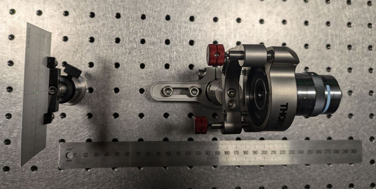
Here we use two mirrors (not shown) to steer a collimated ~1mm 532nm laser beam onto various optics and look at the back reflections with a mobile viewing screen (an alignment card with a ~1mm hole):

Note: Another approach is to have a fixed optical axis (e.g. defined by a fixed laser beam) and to place an optic onto the axis with an adjustable mount. This is typical when building systems with multiple optics that must share the same axis.