SOLS excitation
In a single-objective light-sheet (SOLS) microscope, how should we configure the excitation?
ContentsAdjusting light-sheet thickness
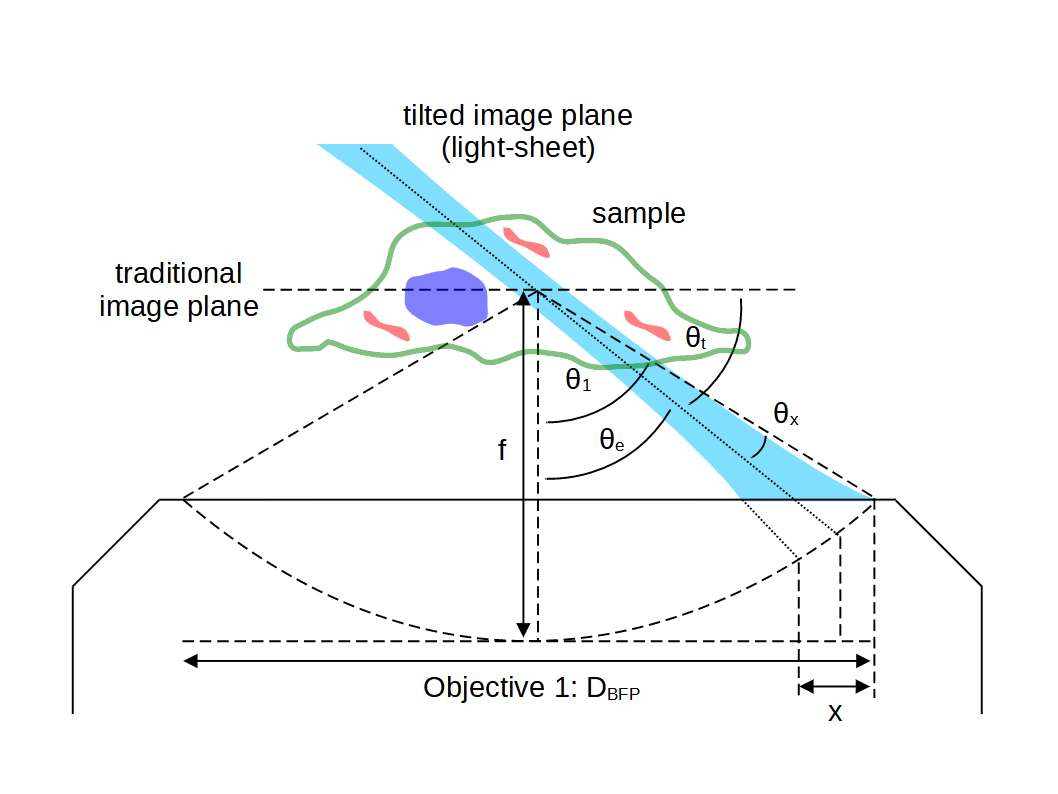
Once the maximum sheet divergence \(\theta_x\) has been calculated (for example by choosing a tilt angle \(\theta_t\) that is sufficient for the thinnest usable light-sheet), it can be useful to see how this angular range translates to a width \(x\) in the back focal plane (e.g. for determining and adjusting excitation optics):

For infinity corrected objectives the ray height in the back focal plane \(r_{BFP}\) relates to the angles in the object space via: \[ r_{BFP} = f n \sin\theta \tag{1}\] So the width of the excitation beam in the BFP is: \[ x = f n [\sin(\theta_e + \theta_x) - \sin(\theta_e - \theta_x)] \tag{2}\] which we can rewrite with \(\sin(a \pm b) = \sin a\cos b \pm \cos a\sin b\): \[ x = f n [\sin \theta_e\cos \theta_x + \cos \theta_e\sin \theta_x - (\sin \theta_e\cos \theta_x - \cos \theta_e\sin \theta_x)] \tag{3}\] which reduces nicely to: \[ x = 2 f n \cos\theta_e \sin \theta_x \tag{4}\] Or in terms of the tilt of microscope 3 (using \(\theta_e = \frac{\pi}{2} - \theta_t\)) and assuming \(\sin\theta_x \approx \theta_x\): \[ x = 2 f n \sin\theta_t \; \theta_x \tag{5}\] If we adopt the tilt and excitation angles (\(\theta_t \) and \(\theta_x \)) from SOLS_optimum_tilt then we can calculate the maximum BFP width for different objectives (see Python script). Here are some examples:
| Make | Mag | NA | n | f (mm) | tilt (deg) | max divergence (deg) | max x (mm) |
|---|---|---|---|---|---|---|---|
| Nikon | 100x | 1.35 | 1.41 | 2 | 25.0 | 8.3 | 0.35 |
| Nikon | 40x | 1.15 | 1.33 | 5 | 37.5 | 7.3 | 1.02 |
| Nikon | 25x | 1.00 | 1.33 | 8 | 47.4 | 6.2 | 1.69 |
The maximum value of \(x\) can now be used to specify a laser beam input \(\frac{1}{e^2}\) waist on this axis \(w_{laser}\), for example by setting: \[ 2w_{laser} = \max(x) \tag{6}\] We can now rearrange (5) for the transverse full width half max of the light-sheet in the sample space (i.e. the thickness): \[ w_{FWHM} = \sqrt{2\ln2} \frac{2 f \sin\theta_t \lambda_0}{\pi x} \tag{7}\] So if \(x\) now corresponds to an adjustable zoom optic, then (7) is an exact calculation. If however, \(x\) is mapped to an adjustable aperture, then (7) is approximate (due to clipping the Gaussian beam). In both cases the mapping of \(x\) to the BFP is asymmetric around the tilted image plane \(\theta_t \), so for large changes in \(x\) a 'light-sheet tilt to image' adjustment may be needed.
The length of sample \(z_s\) over which we can expect to maintain uniform illumination (>90% of the peak intensity) is then: \[ z_s = \frac{\pi n}{3\ln2 \lambda_0} w_{FWHM}^2 \tag{8}\] Note: If the aperture or zoom optic is in a magnified space in relation to the objective 1 BFP (which it usually is), then this magnification factor should be taken into account when considering the size of \(x\). See this Python script for an example based on the original SOLS microscope.